Pipe Network Concept
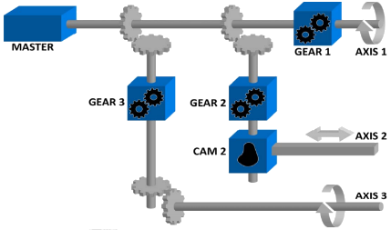
In the figure below, the mechanical system is composed of three-axes and driven by one motor. All axes are connected to the motor through shafts, gears and cams. When the motor is in motion, all axes are moving synchronously. The speed relation between the Master and the Axis is achieved by using a mechanical Gear. A mechanical cam is used to get linear motion from a rotating wheel.
The Pipe Network in the figure below corresponds to the mechanical system described above. The pipe concept is a one-to-one translation of a mechanical system into the logical world.
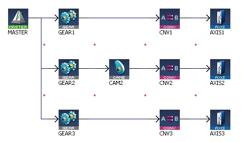
Figure 5-7: Pipe Network Structure
In our Pipe Network, the analogy is as follows:
- The main motor of the mechanical machine becomes a Virtual Master Pipe Block
- The gear boxes becomes Gear Blocks
- The mechanical cam becomes a Cam Block
- The axes becomes Axis Blocks
The Pipe Network concept allows motion engineers to define in a very natural way the physical relationships between the different axes of their machine.
This powerful modular approach provides a solution for almost any multi-axis requirements. It also remains open for new, additional functions that can be required in the future.


